For the MFRU exhibition, we presented a variety of robots. The following is some documentation, on the specifications, and setup instructions. We are leaving the robots with konS.
All Robots
Li-Po batteries need to be stored at 3.8V per cell. For exhibition, they can be charged to 4.15A per cell, and run with a battery level monitor until they display 3.7V, at which point they should be swapped out. Future iterations of robotic projects will make use of splitter cables to allow hot swapping batteries, for zero downtime.
We leave our ISDT D2 Mark 2 charger, for maintaining and charging Li-Po batteries.
At setup time, in a new location, Raspberry Pi SD cards need to be updated to connect to the new Wi-fi network. Simplest method is to physically place the SD card in a laptop, and transfer a wpa_supplicant.conf file with the below changed to the new credentials and locale, and a blank file called ssh, to allow remote login.
ctrl_interface=DIR=/var/run/wpa_supplicant GROUP=netdev
update_config=1
country=si

network={
    ssid="Galerija"
    psk="galerija"
    key_mgmt=WPA-PSK
}
Then following startup with the updated SD card, robot IP addresses need to be determined, typically using `nmap -sP 192.168.xxx.xxx`, (or a windows client like ZenMap).
Usernames and passwords used are:
LiDARbot – pi/raspberry
Vacuumbot – pi/raspberry and chicken/chicken
Pinkbot – pi/raspberry
Gripperbot – pi/raspberry
Birdbot – daniel/daniel
Nipplebot – just arduino
Lightswitchbot – just arduino and analog timer
For now, it is advised to shut down robots by connecting to their IP address, and typing sudo shutdown -H now and waiting for the lights to turn off, before unplugging. It’s not 100% necessary, but it reduces the chances that the apt cache becomes corrupted, and you need to reflash the SD card and start from scratch.
Starting from scratch involves reflashing the SD card using Raspberry Pi Imager, cloning the git repository, running pi_boot.sh and pip3 install -y requirements.txt, configuring config.py, and running create_service.sh to automate the startup.
LiDARbot

Raspberry Pi Zero W x 1
PCA9685 PWM controller x 1
RPLidar A1M8 x 1
FT5835M servo x 4
Powered by: Standard 5V Power bank [10Ah and 20Ah]
Startup Instructions:
– Plug in USB cables.
– Wait for service startup and go to URL.
– If Lidar chart is displaying, click ‘Turn on Brain’
It is able to not bump into things.
Vacuumbot

Raspberry Pi 3b x 1
LM2596 stepdown converter x 1
RDS60 servo x 4
Powered by: 7.4V 4Ah Li-Po battery
NVIDIA Jetson NX x 1
Realsense D455 depth camera x 1
Powered by: 11.1V 4Ah Li-Po battery
Instructions:
– Plug Jetson assembly connector into 11.4V, and RPi assembly connector into 7.4V
– Connect to Jetson:
cd ~/jetson-server
python3 inference_server.py
– Go to the Jetson URL to view depth and object detection.
– Wait for Rpi service to start up.
– Connect to RPi URL, and click ‘Turn on Brain’


Pinkbot

Raspberry Pi Zero W x 1
PCA9685 PWM controller x 1
LM2596 stepdown converter x 1
RDS60 servo x 8
Ultrasonic sensors x 3
Powered by: 7.4V 6.8Ah Li-Po battery
Instructions:
– Plug in to Li-Po battery
– Wait for Rpi service to start up.
– Connect to RPi URL, and click ‘Turn On Brain’
Gripperbot

Raspberry Pi Zero W x 1
150W stepdown converter (to 7.4V) x 1
LM2596 stepdown converter (to 5V) x 1
RDS60 servo x 4
MGGR996 servo x 1
Powered by: 12V 60W power supply
Instructions:
– Plug in to wall
– Wait for Rpi service to start up.
– Connect to RPi URL, and click ‘Fidget to the Waves’
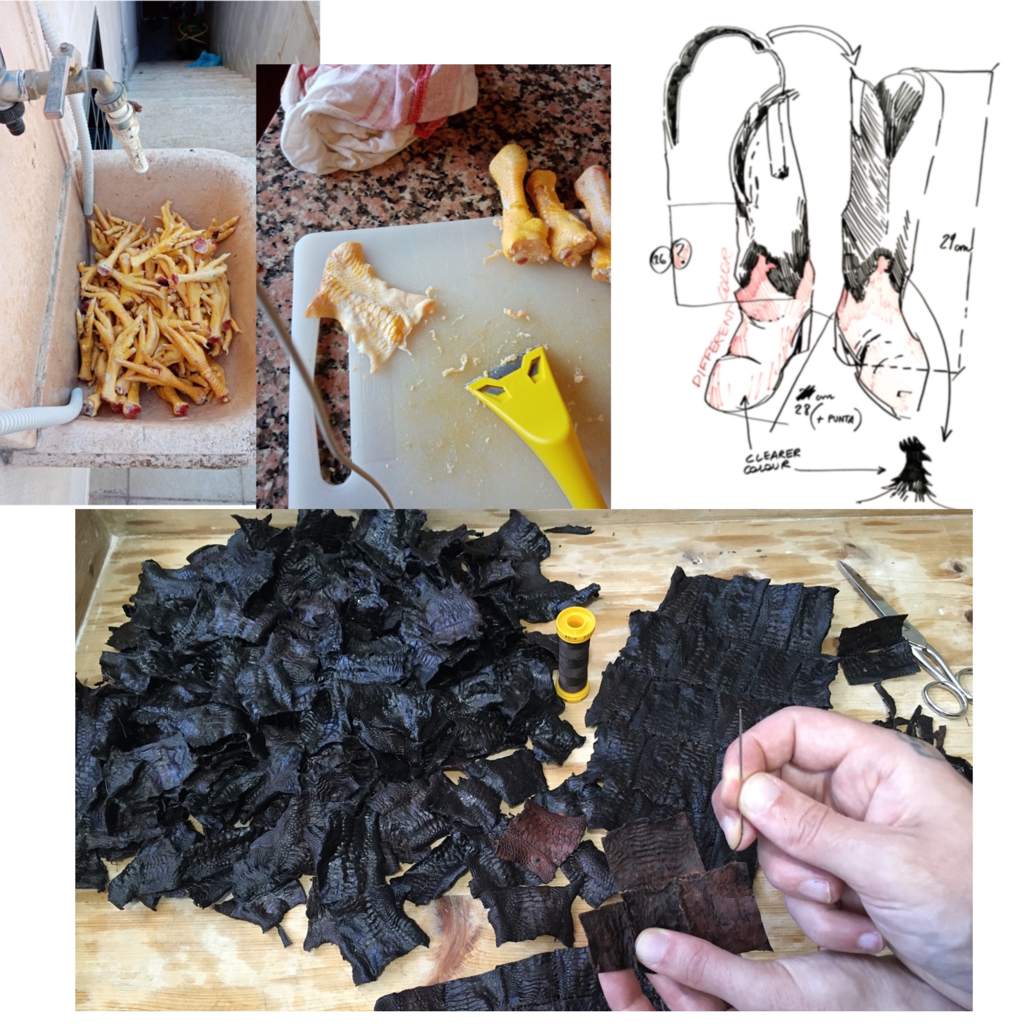
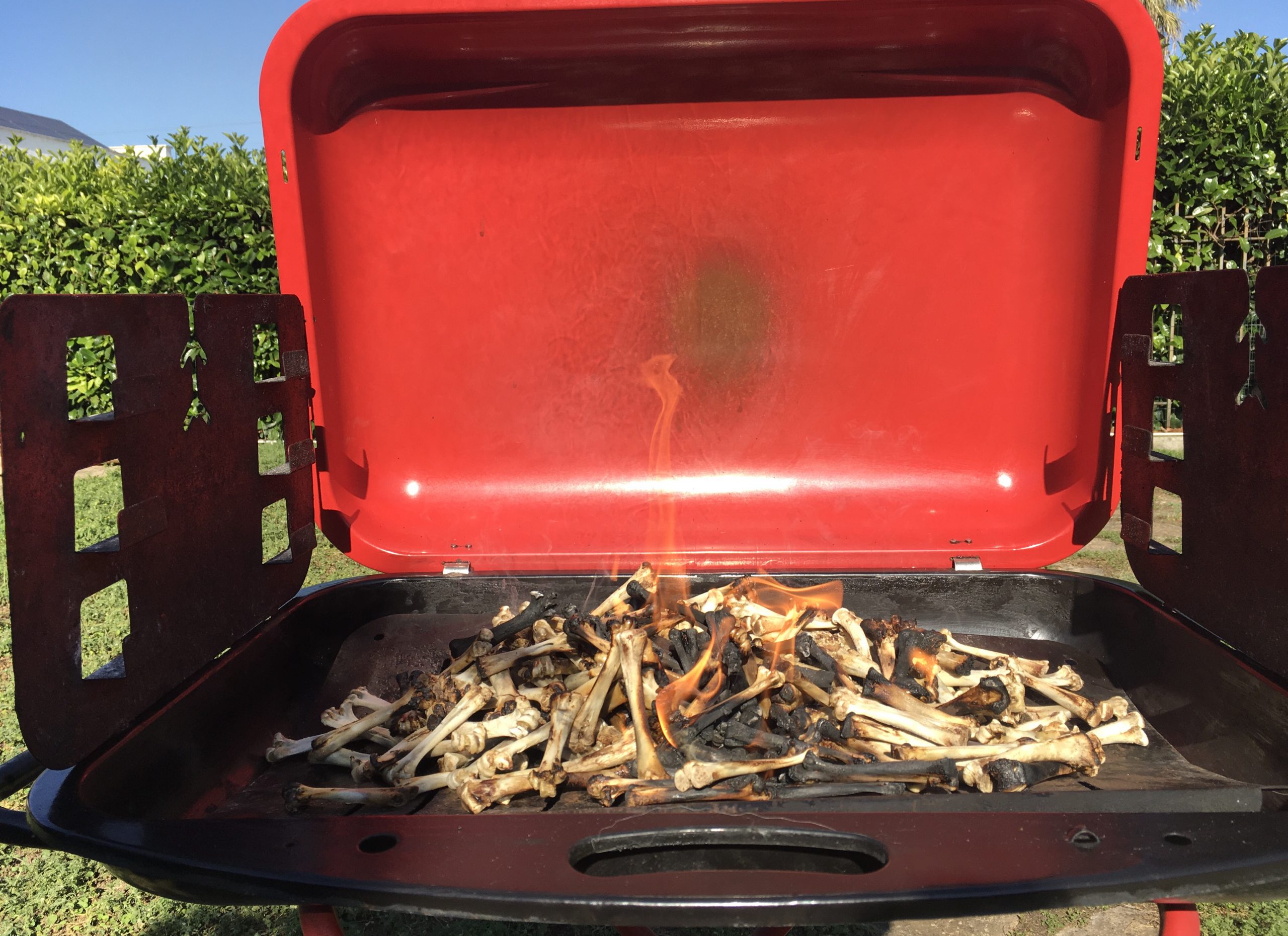
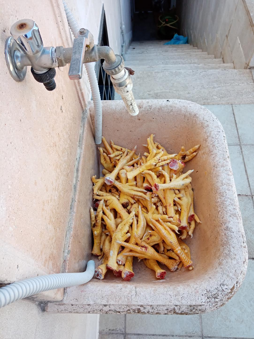
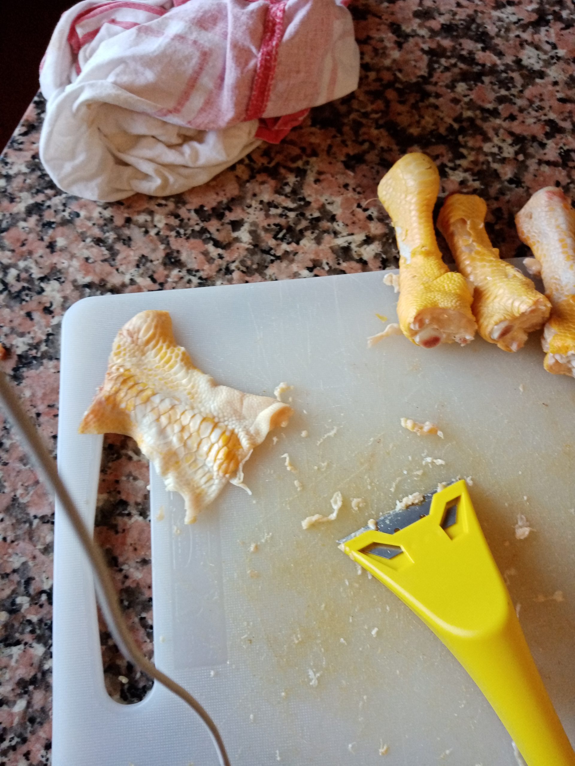
Birdbot

Raspberry Pi Zero W x 1
FT SM-85CL-C001 servo x 4
FE-URT-1 serial controller x 1
12V input step-down converter (to 5V) x 1
Ultrasonic sensor x 1
RPi camera v2.1 x 1
Powered by: 12V 60W power supply
Instructions:
– Plug in to wall
– Wait for Rpi service to start up.
– Connect to RPi URL, and click ‘Fidget to the Waves’


